Simulation
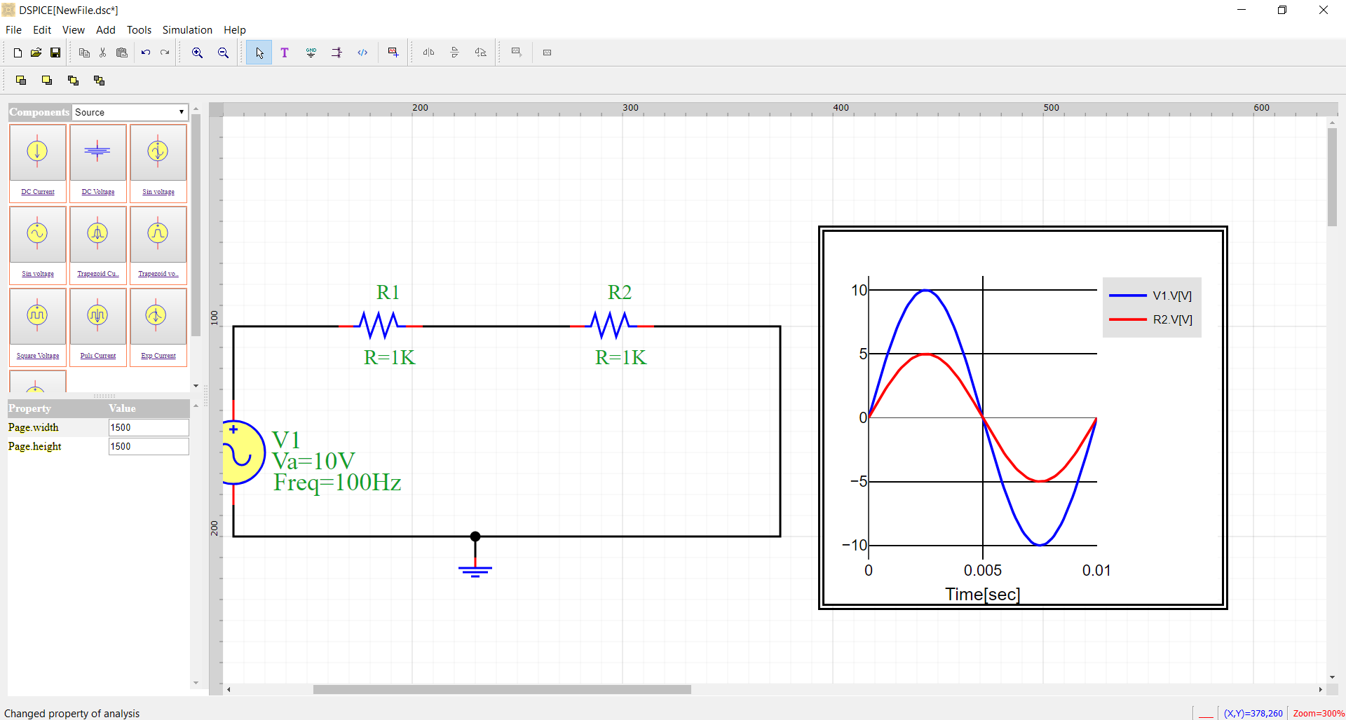
The graphical user interface (GUI) of DSPICE is presented in Fig. 1.
Fig. 1 IDE of DSPICE
The objectives of this interface are:
Drawing circuit by schematic (CAD approach);
Modifying parameters of elements by using an intuitive language;
Simulating the circuit in the selected mode of operation.
Presenting simulation results in a probe or in a waveform.
The steps of simulation by DSPICE
The simulation of circuits in DSPICE is based by Graphical user interface in six steps:
Step a. Add Symbol in schematic
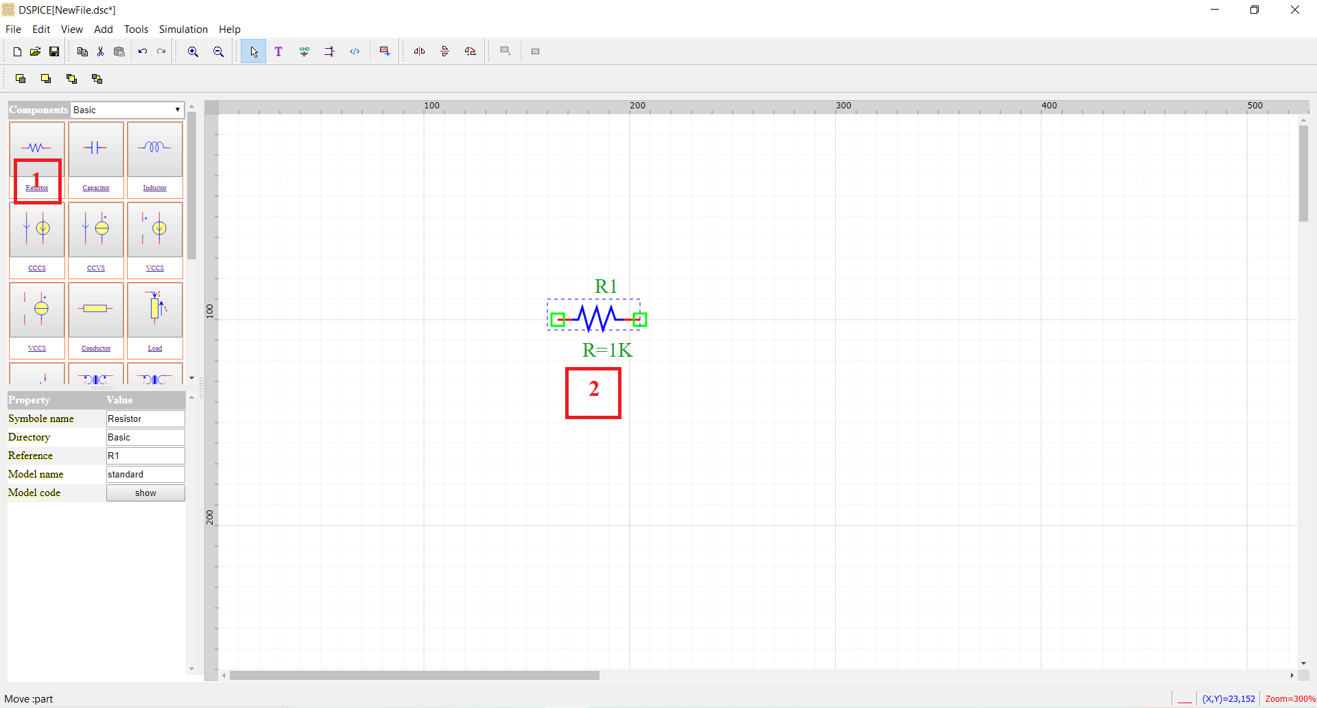
Click the symbol in the components list;
Click the position in the schematic;
Step b. Linking elements by wire
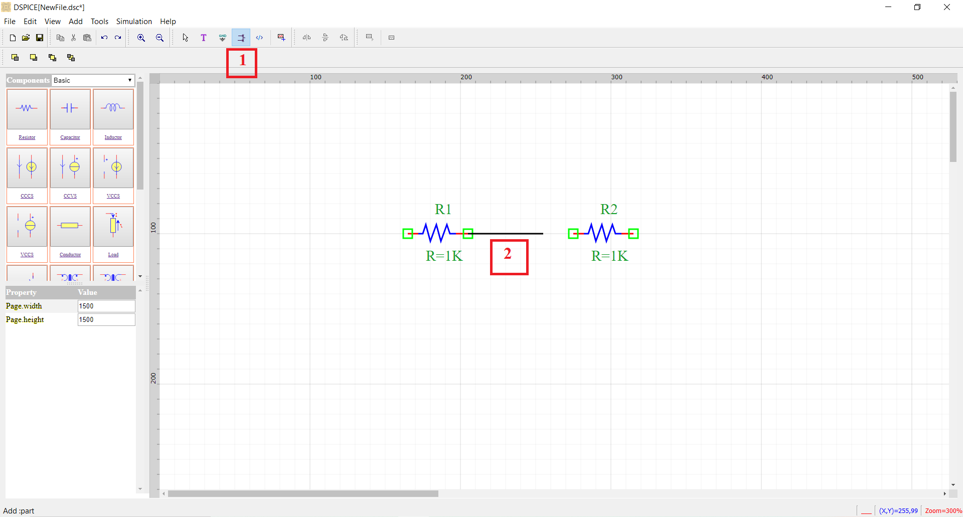
Click on the wire icon;
Connect the pins;
Step c. Modifying parameters of elements
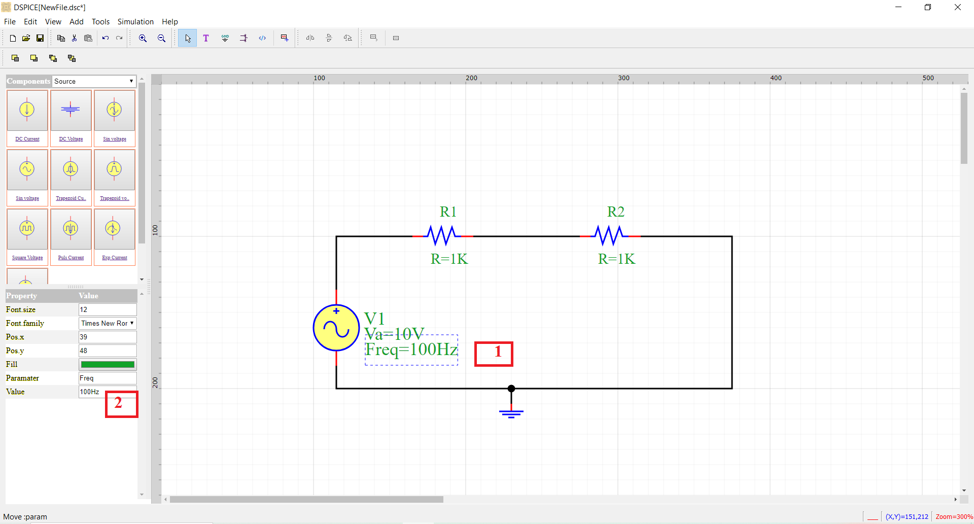
Click on the value
Change of value
Step d. Adding a analysis in the circuit with adjusting type of analysis and add outputs
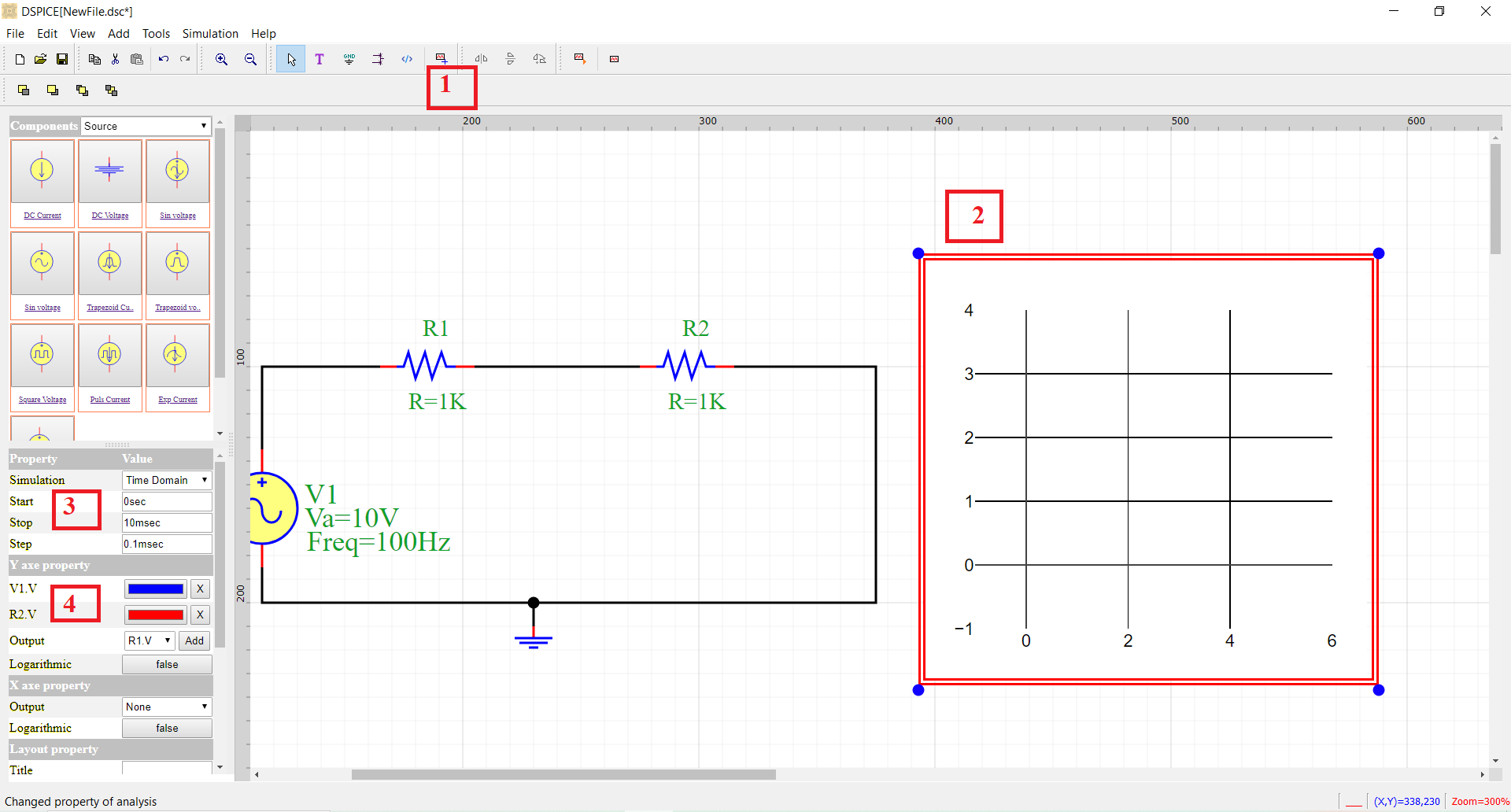
Click on the analysis icon
Select Analysis
Select the type
Add outputs
Step e. run circuit
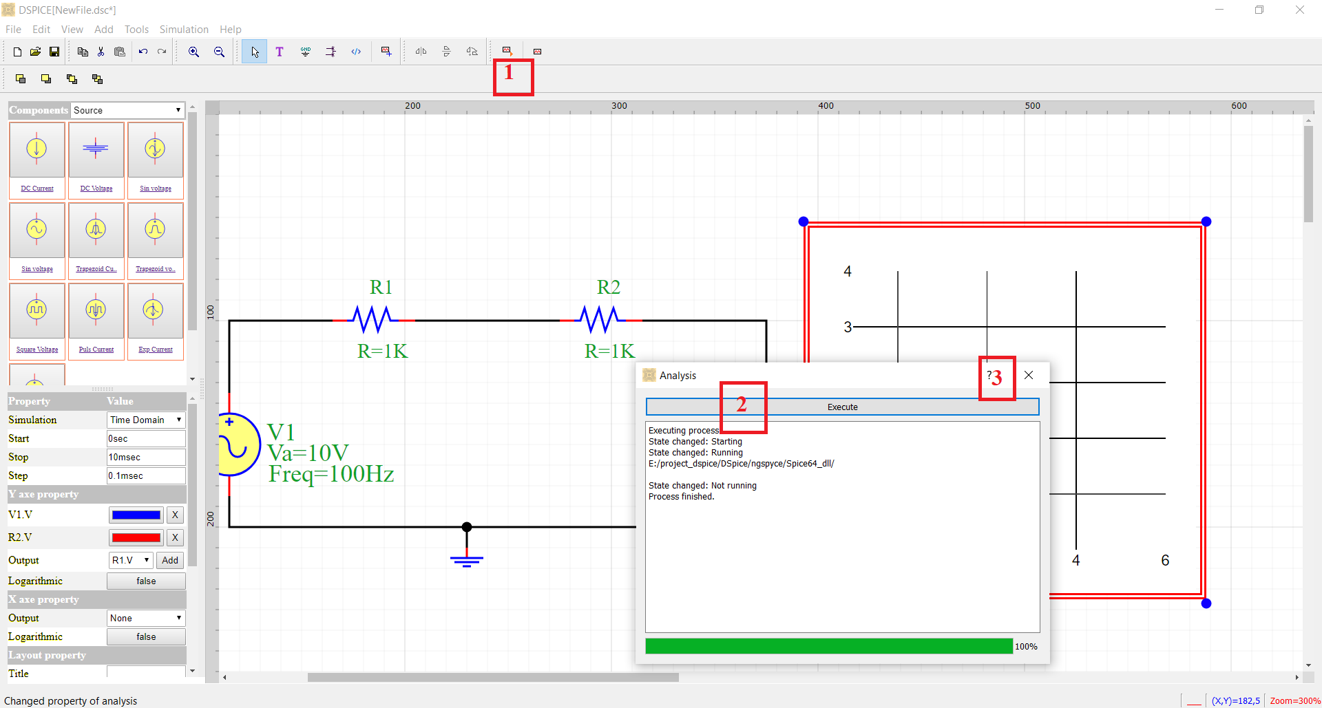
Click on the analysis command icon.
Click Execute in the dialog box.
Exit.
Step f. results