Design symbols
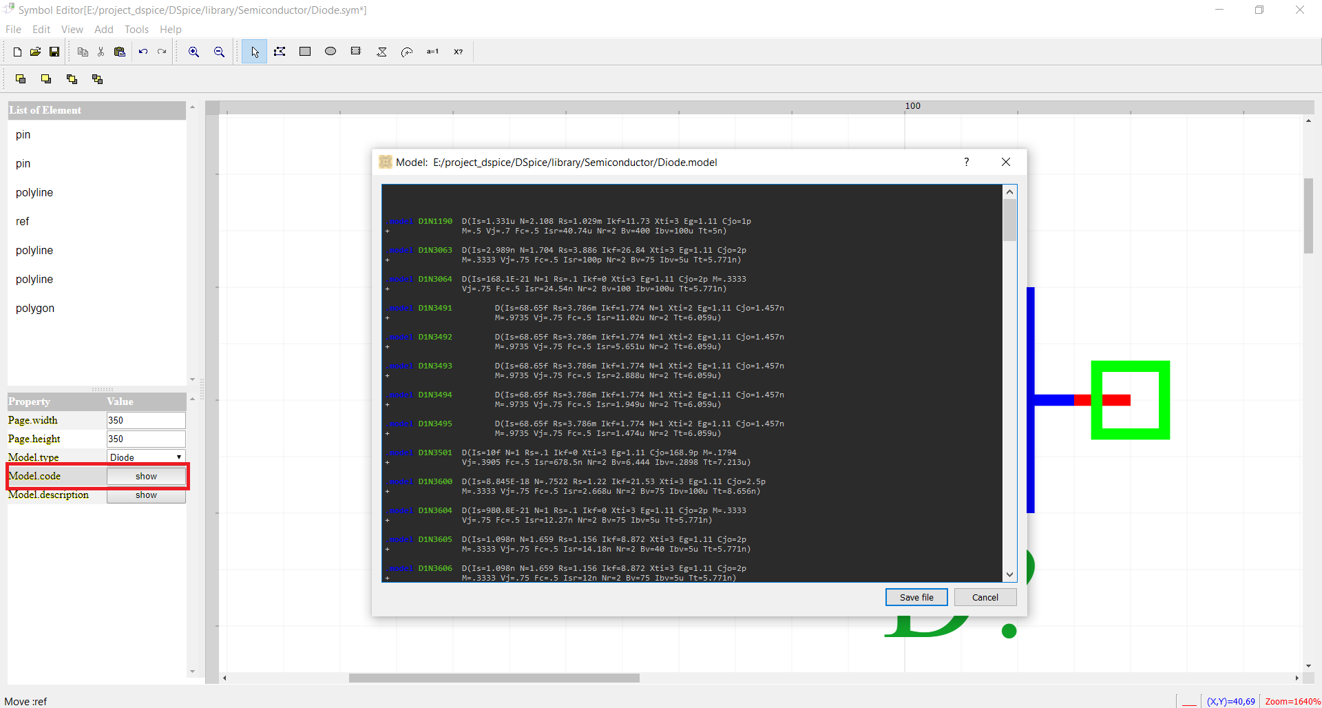
The analog elements in the circuit are designed by the symbol editor (Fig. 1) it presented SPICE model.
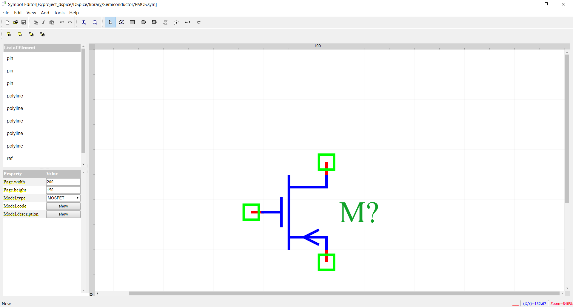
Fig. 1 symbol editor
The steps of design symbol
The creating of symbols in the editor is based on the following steps:
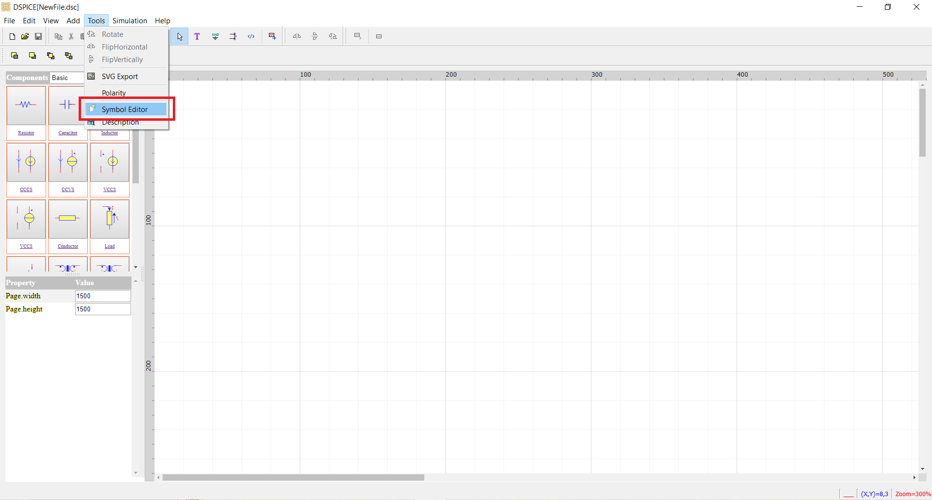
Step 1 Execute: SymbolEditor from DSPICE
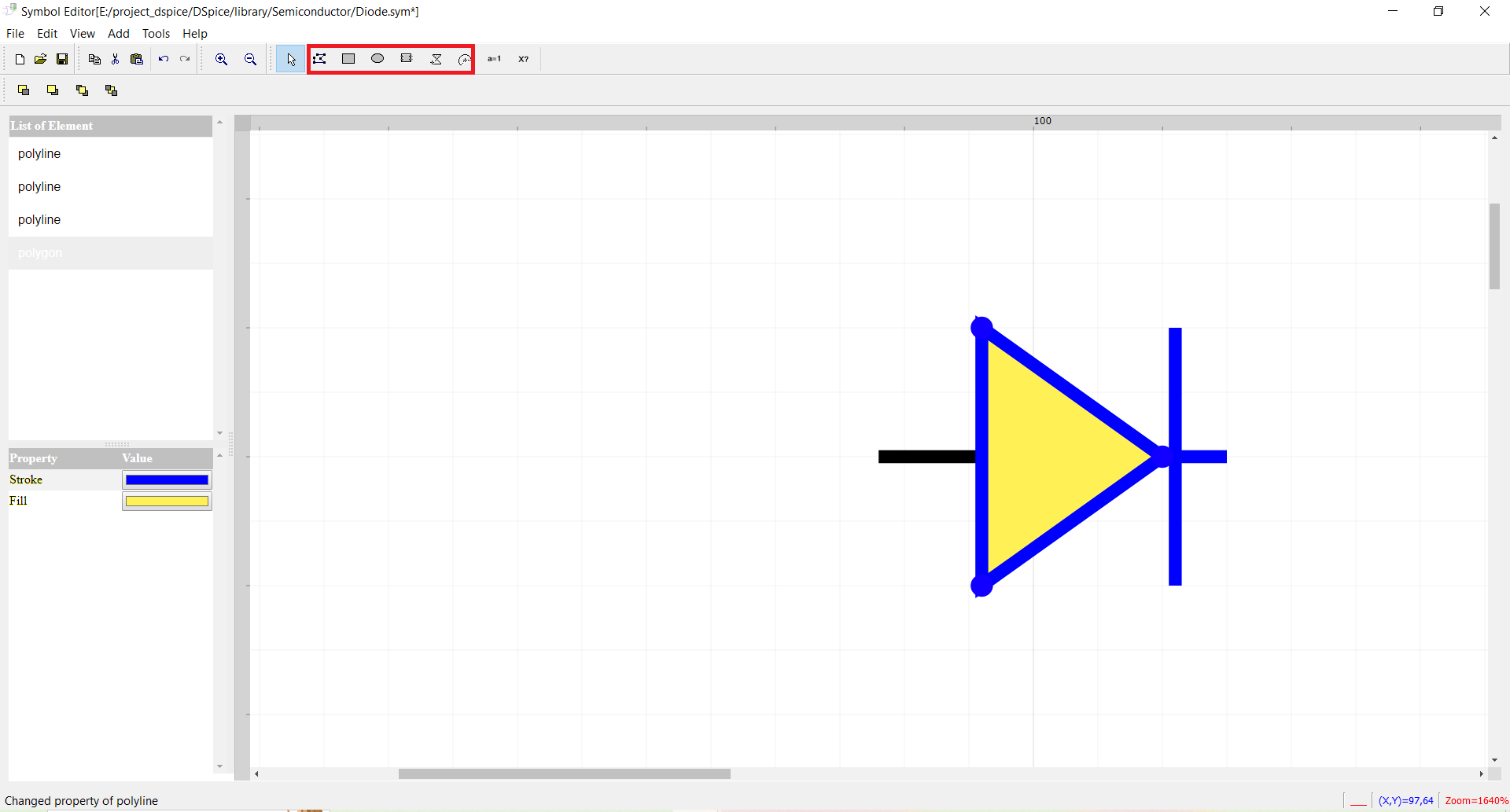
Step 2 Draw the electrical elements by lines, rectangles, ellipse ….etc.
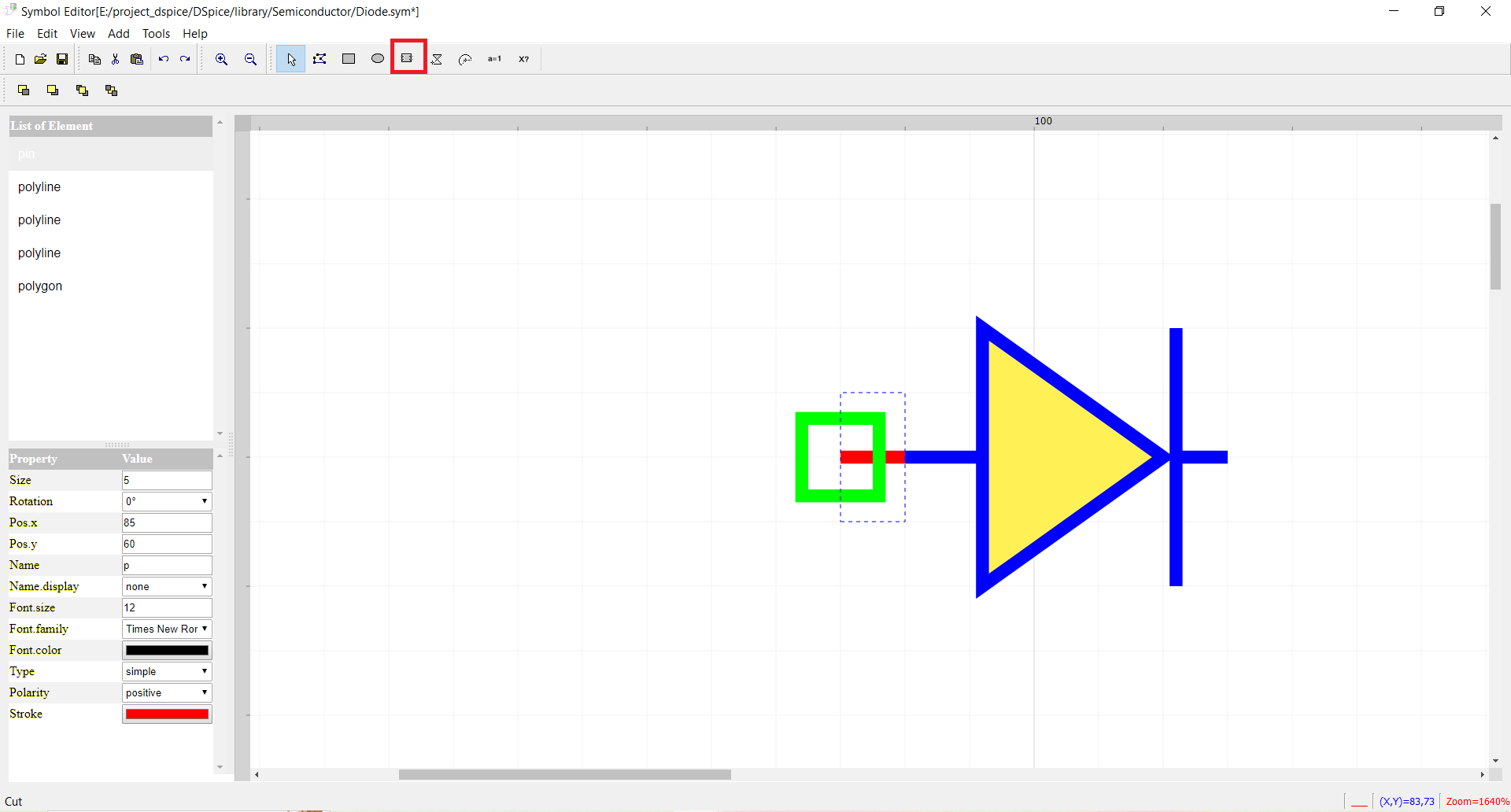
Step 3 Add ports or pins.
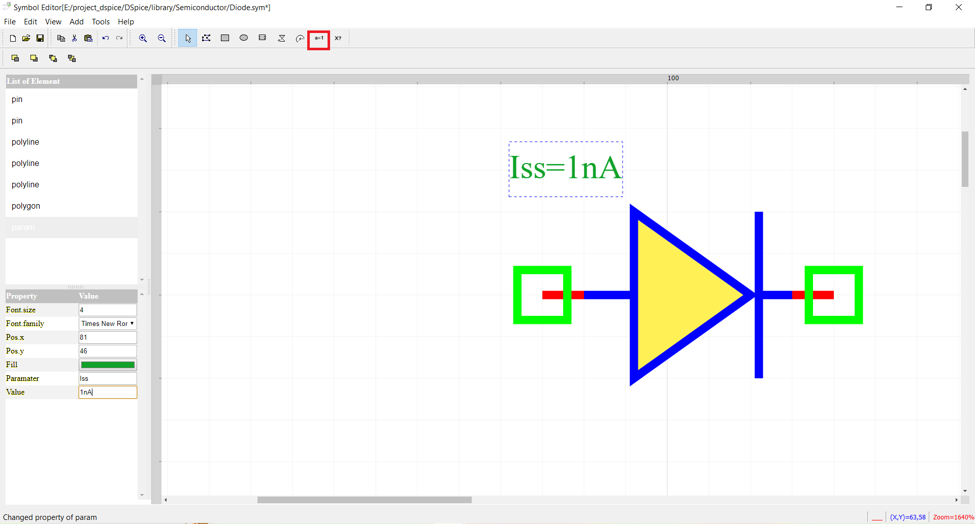
Step 4 Add parameters.
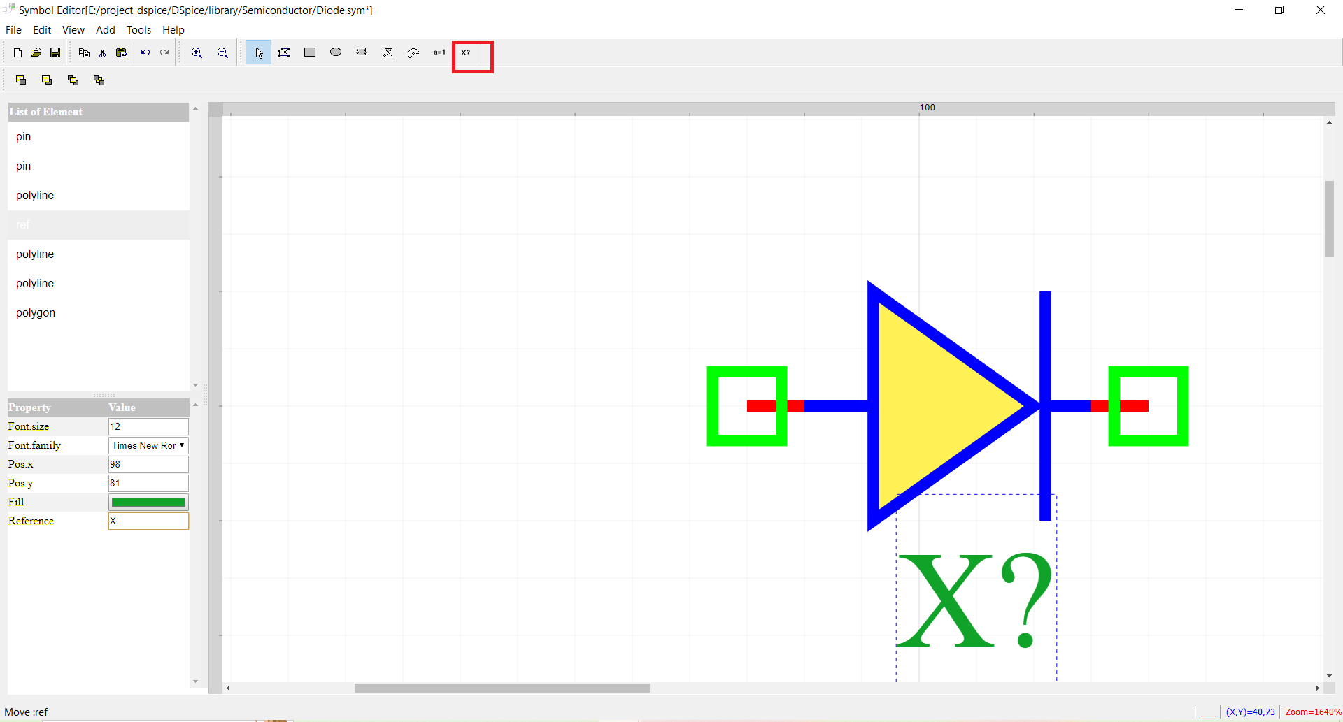
Step 5 Add reference.
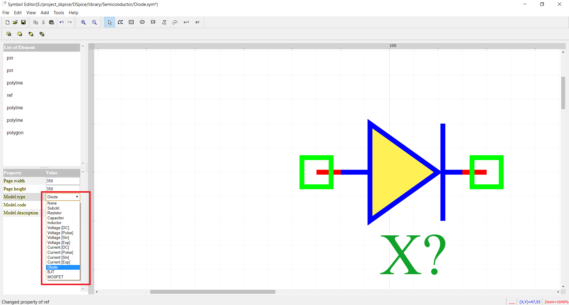
Step 6 Choose the type of model.
Step 7 Save the new symbol in one of the folders in the library.
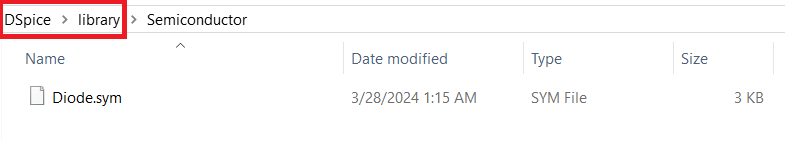
Step 8 Write SPICE model.
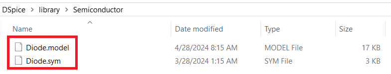
Step 9 Or attach symbol with SPICE model by placed or saved in the same directory with the same name of model (with extension *.model).